Non-contact tools increase electrical safety
March 25, 2014
By Randy Barnett
Limiting worker exposure to the electrical hazards of shock and arc flash is the foundation of any electrical safety program. Using test leads and clamps to probe inside of a live panel when troubleshooting and performing routine maintenance always exposes workers to danger. Electrical Personal Protective Equipment (PPE) is a last line of defence and must never be relied upon as the primary method of protecting electricians and technicians. Safe work practices, including the use of non-contact test tools that do not require electrical workers to place themselves in harms way, must first be considered when it comes to electrical safety.
Anytime workers are exposed to electrical hazards they are required to establish boundaries and wear the appropriate arc-rated clothing and rubber insulating gloves. Safely reducing the amount of PPE worn, reducing the number of workers inside the boundary and even completely moving the test technician or electrician outside of all boundaries and away from potential danger are the major safety advantages of non-contact measurements.
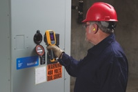
Among the simplest non-contact test tools to use are the non-contact infrared (IR) thermometers. Using the tool’s pistol grip to point a laser beam where the temperature is to be measured produces a temperature reading on the display. The laser beam is only for “aiming” the tool at the area to be measured. The temperature detected depends upon the tool’s distance from the point of measurement. Care must be taken to achieve accurate results.
When it comes to safety, using an IR thermometer means no climbing on ladders to check ventilation exhaust temperatures, no reaching around hot temperature bands and barrels to troubleshoot process problems, no reaching around rotating shafts to check for motor hot spots, and no reaching inside of live panels to check temperatures of components.
A more advanced, yet practical non-contact IR thermometer is the visual IR thermometer. In addition to the standard IR thermometer features, the visual thermometer provides a digital image creating an infrared heat map – somewhat like a thermal imager. The visual IR thermometer is more accurate than the standard IR thermometer as it does not average in surrounding areas. Instead, the heat map is blended with a standard digital image so problem areas can be readily identified. Digital images can also be downloaded to a computer for further analysis and report generation, allowing work to be done at safe distances well beyond shock and arc flash boundaries.
The heat map of the visual IR thermometer allows for quick identification of overheated conductors and terminations – potential fire hazards. Overheated contacts and electrical components could indicate pending equipment failures and possible arc flash issues. Identifying and reducing hazards is a goal of every safety program.
Thermal imagers, sometimes called infrared cameras, not only capture and measure the infrared (heat) energy emanating from a source, but produce a thermal image as well. Colours are used to indicate the degree of heat coming from various components when viewing the screen. Viewing a thermal image, especially when the standard digital image of the source is fused with the thermal image, produces a user-friendly picture for identifying potential problems. The operator can readily distinguish the difference in temperatures across the source image and quickly determine if corrective action is needed, and even how soon.
For example, when performing a thermal scan of electrical equipment, the International Electrical Testing Association (NETA) notes that if a temperature difference between similar components under similar loading is between four degrees C and 15 degrees C, there is problem with the higher temperature component and it should be repaired when possible. However, if that temperature difference between the similar components increases to greater than 15 degrees C, then immediate repairs should be completed.
Imagine one terminal on a three-phase breaker running significantly more than 15 degrees C hotter than the other two phases. Such an indication could mean that a very high resistance at the terminal is producing dangerously high heat, insulation is beginning to soften and deform, and the breaker itself is near catastrophic failure. A non-contact measurement with a thermal imager identifies the potential failure in real-time and, most importantly, keeps the technician at a much safer distance while diagnosing a potentially dangerous problem.
A trained thermographer can function as part of a two-man team for thermal scans (an additional qualified person to assist with setting up boundaries and opening enclosure doors), that can quickly move through a facility identifying overloaded circuits, faulty electrical and rotating mechanical equipment, and thermal process issues. Averting potential safety problems by correcting before failure is another component of a safe work environment.
Using an infrared (IR) window in conjunction with a thermal imager widens the safety envelope even further. Relatively small, circular IR windows can be permanently installed on enclosures that are part of the plant’s thermal imaging program, or can be mounted on equipment enclosures that may produce a dangerous arc flash should an accident occur while the door is open. By scanning through an IR window that is rated to withstand an arc flash and blast, it is not even necessary to open an enclosure door to scan. As a result, there is virtually no technician exposure to shock or arc flashes.
One tool that is often overlooked when it comes to safety is the laser distance meter. Generally considered only as a convenience item, this non-contact distance measurement tool also increases safety when doing such jobs as conducting an arc flash study. This engineering analysis requires measuring the lengths of conductor runs between equipment. Rather than using steel measuring tapes and stepladders with two people finding themselves in precarious positions near and over cable trays and switchgear, the laser distance meter allows many distance measurements to be taken safely from the floor by just one person. Press the measure button once and the laser is activated. Then, point the laser to where the distance is to be measured and press the measure button again to read an accurate distance of up to 200 feet or more on the display.
Non-contact voltage detectors allow voltages to be detected without having to make contact with an energized part. For quick power checks at a receptacle or troubleshooting a lighting circuit, the voltage detector is safer than placing probes in a receptacle and much safer than opening boxes and lighting fixtures. Users must be aware that voltage detectors will only indicate power on the ungrounded side of the circuit; not the grounded or neutral conductor side.
Remote display multimeters allow readings to be taken up to 30 feet away from the equipment being monitored. The display unit is removed from the multimeter while the meter and probes (or clamp) remain at the point of measurement. Safety applications include closing the door on an MCC cubicle or disconnect and standing at a safe distance to measure motor inrush current. Standing directly in front of a motor starter when a large three-phase motor draws many times its normal running current at startup is no place to be, even if wearing the appropriate PPE. Once again, the use of non-contact tools greatly reduces the personnel risk.
Wireless tools provide the most advanced technology for enhancing safety. Three remote modules are set up at the equipment to be monitored. The DMM itself, with its display, can be held and observed at a safe distance more than 60 feet away where it receives the wireless signals. If desired, up to 10 readings can be downloaded in real time wirelessly, directly from the modules to a laptop.
Technicians can stay well outside any shock or arc flash boundaries as equipment is operated and various parameters are observed and recorded. Many troubleshooting motor control tasks are classed as Hazard Risk Category 2, requiring the use of an arc-rated face shield and balaclava. Once the modules are installed, the hazard risk category can be dropped to zero with the need for cumbersome faceshields, uncomfortable balaclavas and bulky rubber insulating gloves all eliminated. Taking several readings simultaneously helps minimize the need for workers to re-enter the limited approach and arc flash boundaries.
The use of non-contact test tools greatly limits and oftentimes completely eliminates the need for workers to be exposed to the electrical hazards of shock, arc flash and blast. Probing inside of a live panel with hands, test leads and clamps while attempting to locate measuring points, and then placing and holding test leads while turning and leaning to read a meter display carries its own set of hazards. Many times two workers are required to accomplish this task with the additional worker thus being exposed to the hazards. Providing a practical safe working area free of electrical hazards is the stated purpose of electrical safety standards. The use of non-contact test tools can help achieve that goal and create an electrically safe and more efficient work environment for employees.
Randy Barnett has more than 35 years of industrial electrical maintenance and training experience. He is a graduate of the U.S. Navy Nuclear Power School and learned the industrial electrical trade as an electrician in the submarine service. He has worked as a journeyman electrician in nuclear and coal-fired power plants, on railroad locomotives, in industrial manufacturing environments and in commercial and industrial construction. Randy is a certified energy auditor and author of “Commercial and Industrial Wiring,” “Introduction to Electrical Maintenance” and numerous articles. He can be reached at Randy@RandyBarnett.net. In Canada, please contact Colin Plastow, Industrial Product Manager with Fluke Electronics Canada. Colin can be reached at colin.plastow@fluke.com.