Choosing the right lighting technique for your machine vision application
May 24, 2016
By John Lewis Cognex

May 24, 2016 – Machine vision systems create images by analyzing the reflected light from an object, not by analyzing the object itself. Selecting the correct lighting technique can go along way in dealing with the special issues of a particular application. Many options are available, each with pros and cons. Here are five basic techniques for lighting parts to be inspected.
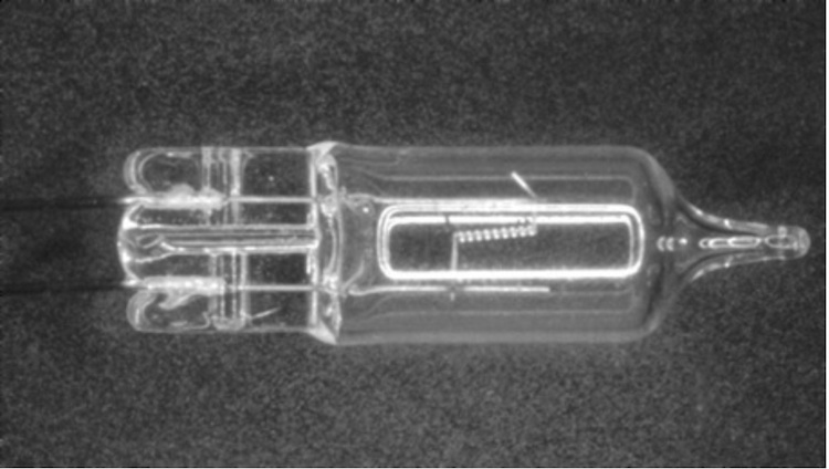
Back lighting creates a silhouette to accentuate the shape of a part and allows for its measurement, but totally obscures all surface detail. It creates the maximum amount of contrast by producing an image that is, for the most part, black on white. Inspection applications can use this technique for making dimensional measurements, but it would be useless for surface inspection. A challenge to this technique is the difficulty in fixturing. Any mechanical fixture that must hold the part being inspected could obstruct the back light; refer to the images below.
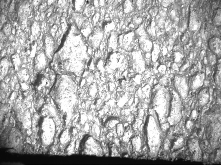
The second lighting technique is direct front lighting. Typically, the light is illuminating from a slightly off-centre angle. It is easy to set up such a lighting source and it can create excellent contrast, however it can also create shadows or produce glare depending on the surface of the part being inspected. Creating shadows may be desirable to enhance contrast where low-contrast images are a problem. And, direct lighting may be used to freeze motion with strobes. For an example of the effect of moving the light source, consider the images here.
If shadows are to be minimized, more than one direct light can be used. For this purpose, some systems use a ring light, which totally surrounds the part being viewed.


Photos: Cognex
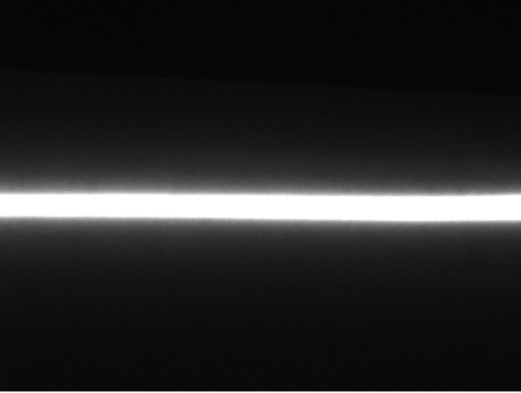
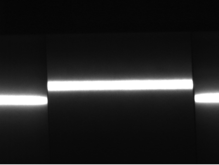
Another lighting technique is structured lighting. Structured lighting makes use of a known light pattern (normally a plane of light creating a line) that is used to obtain dimensional information. Typically highly-collimated light sources are used, such as lasers or fiber optic line lights. This technique is an inexpensive way to measure depth and height of continuous surfaces and is often used when the light source or the surface is moving. It can also show surface details on low-contrast parts. One should make sure that the part being measured does not absorb light, however, since reflection is required for the lighting’s effect on the part to be measured. The effect of a linear light source being reflected off of perfectly flat and non-continuous surfaces is shown in the images here.
Diffuse on-axis lighting, also knows as DOAL, allows for light to be shone directly at a part in line with the camera, without the light source getting in the way of the camera. This is accomplished using a 50-per-cent silvered mirror to reflect light directly at the part. The camera sees through the mirror to capture the image of the part being illuminated.
Diffuse on-axis lighting applications include detecting flaws on shiny, flat surfaces or inspecting the insides of small cavities. Since DOAL lights lose intensity through the silvered mirror, it may be advisable to use an additional lighting source to improve the illumination or the consistency of light on the subject.
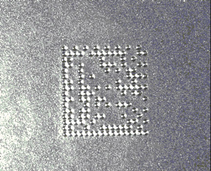
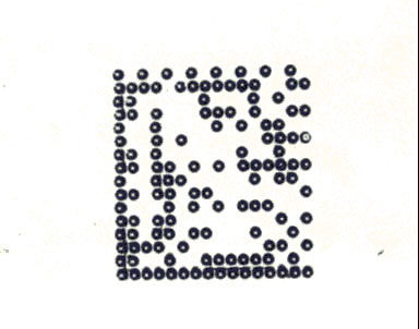
These images show how using DOAL can eliminate reflected glare, making it easier to inspect surface features in some applications.
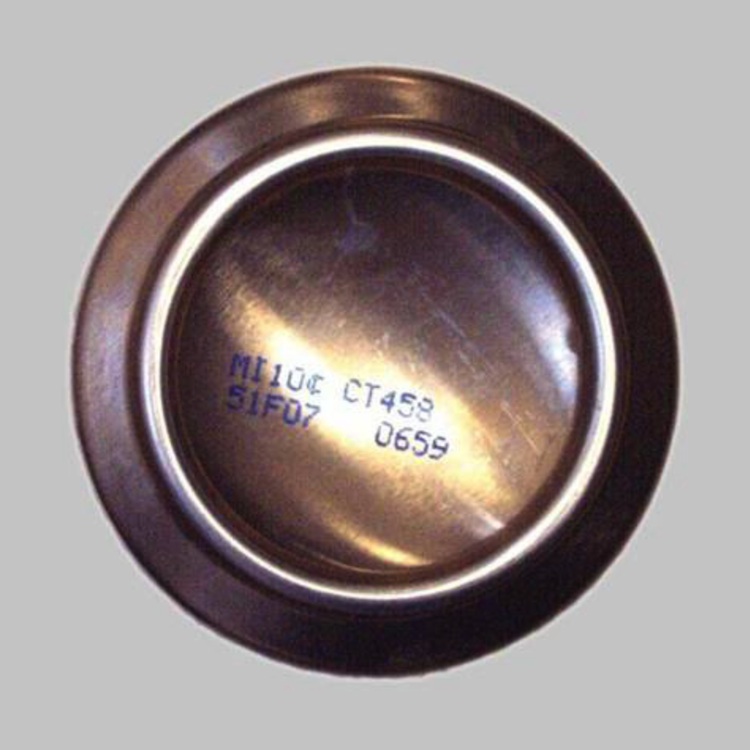
The last lighting technique explained here is diffuse off-axis lighting, also known as cloudy day lighting or dome light illumination. With this technique, the light is not reflected directly onto the part, but first onto a diffuse surface and then it is “bounced” onto the part.
The diffused off-axis technique negates shadows as if one was looking at something on a cloudy day. It also avoids creating hot spots or glare that can cause problems in part inspection applications. When a dome light is used, where the camera shoots through a hole in the reflector dome, there can be a dead spot in the centre of the image. Therefore, when a reflector is used, it may be advantageous to add a DOAL source to fill in the dead spot.
For applications that are space-constrained, flat dome lights are available to place between the camera and the part, producing similar results to curved ones.
Summary
There are many lighting options available and many different ways to construct and orient the vision system. The combination of the lighting source and how it is placed respective to the part and the camera can negate or accentuate features as appropriate to ensure that good, consistent images are produced to meet the inspection requirements of the application.
John Lewis is the market development manager at Cognex. He has written about machine vision and factory automation since 1996 and holds a B.S. degree in chemical engineering.
This article was originally published in the March/April 2016 issue of Manufacturing AUTOMATION.
Advertisement
- Industrial millennials: How to attract millennials and simultaneously boost your business
- Projected success: Five project management lessons for manufacturing