Developing motion control and positioning for vacuum applications
July 13, 2021
By Stefan Vorndran
How motorized positioners meet requirements of vacuum applications through manufacturing and quality control processes
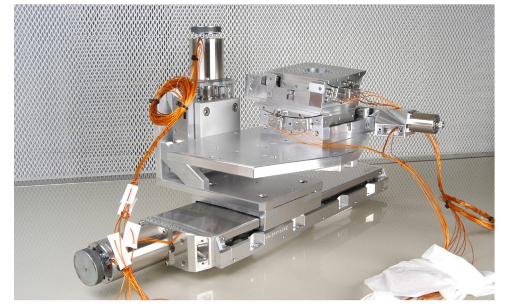 Figure 1: Four-axis system for an ultra-high vacuum application. Photo: PI
 Applications in scientific research and industrial production often require motion and positioning in a vacuum.
Several factors influence the quality of the vacuum environment. One of the main challenges is outgassing of the components used. Manufacturers address this by providing standardized vacuum-ready or customized products that meet the requirements of high-vacuum (HV) and ultra-high-vacuum (UHV) applications.
This article focuses on motorized positioners for vacuum applications and describes how those are designed, manufactured and tested regarding their specific requirements.
Vacuum applications
Vacuum applications are becoming increasingly important because of new technologies that can only be used in a vacuum. For example, lenses are coated in the optics industry and in fibre and laser optics as well, as sensitive detectors are manufactured in a vacuum.
In the production of micro-electronic circuits, vacuum conditions ensure safe handling of sensitive components. Both the aerospace industry and the automotive industry use electron beam processes to minimize angular distortion and transverse shrinkage during welding of micro-components or thick-shelled workpieces.
The surface and material analysis, with the help of scanning electron microscopy (SEM), transmission electron microscopy (TEM) or X-ray tomography, must be done in a vacuum. Nanocharacterization and nanostructuring are also dependent on a vacuum environment due to the methods used, such as ion-beam focusing.
Ultra-high vacuum and very clean conditions are required for EUV lithography that is intended to allow further reduction of feature sizes in the semiconductor industry, and also the development of qubits for advancing quantum computing would be unthinkable without vacuum technology.
Both scientific research and industry require different vacuum classes for all of these and many other applications, and the appropriate equipment must be provided.
There are clearly defined challenges for operating positioning systems. One of them is typically limited installation space. It is also important to avoid contaminating the vacuum chamber with particles by abrasion or outgassing, as well as excessive heat input.
Manufacturers of motion control and precision positioning equipment that are experienced in vacuum technology and applications can offer standard and customer-specific drive technologies that are precisely tailored to the requirements of the vacuum application (as shown in Figure 1, above).
This includes motorized positioners with specially designed DC or stepper motors that allow large travel ranges. Furthermore, piezo actuators, piezo systems and piezo motors, as well as parallel kinematic hexapods, are also available in different designs with respect to force, dynamics and travel ranges.
Challenges in vacuum
It is important to analyze the demands of a specific application in order to select the required vacuum class. Additionally, to the final pressure, the outgassing rate is relevant because it determines the partial pressure of specific residual components.
For example, HCs (hydrocarbons) may be introduced into the vacuum chambers unintentionally due to the use of grease or plastic components not compatible for use in a vacuum. HCs are fragmented by strong UV light or X-rays, and therefore, they are especially critical in laser applications in the UV range and in beam-line applications. HC fragments deposited on optics surfaces pollute or can even damage the in-vacuum optics or the test sample.
Vacuum classes
Vacuum is defined as pressure lower than normal atmospheric air pressure (DIN 28400), and is measured in either [hPa], [mbar] or [Torr]. Different levels of vacuum classes are defined: fine, high, ultra-high and extreme. While high and ultra-high are commonly applied, extremely high vacuum is rarely necessary. To determine the required vacuum class, it is necessary to know the application as well as possible (as shown in Table 1).
Table 1 – Definition of vacuum classes based on pressure ranges. (PI)
Outgassing rate
The outgassing rate is the next relevant specification because it represents the partial pressure of specific residual components. Outgassing is the detachment of volatile molecules that are absorbed or adsorbed on the surface, or in the volume of a material.
Because the rate of outgassing defines the pressure in the system (together with the capacity of the vacuum pump), outgassing prohibits fast achievement of low-pressure values. In addition, the outgassing compounds deposit on surfaces of optical elements or other sensitive devices and can obscure or damage them.
Overall, motorized positioners are required with low outgassing. Furthermore, the residual gas must contain very little or no HCs, and no metals with high vapour pressure such as zinc, lead or cadmium.
Vacuum-compatible equipment
Because outgassing is a challenge for creating and maintaining clean high-vacuum environments, the right choice of materials and treatments is compulsory in the design and production of vacuum systems.
To achieve a high-vacuum- (HV) or an ultra-high-vacuum- (UHV) compatible motorized positioner, three main issues have to be considered: material selection, design, and the manufacturing and commissioning processes.
Manufacturers offer specific vacuum-ready catalogue items for selected product series that are already compatible for HV or UHV, or can be modified on request for use in a vacuum.
Vacuum-ready motorized positioners
Using Physik Instrumente (PI) as an example, there are three specific standard vacuum classes the company makes available: V6 for high-vacuum specifications, V7 for higher cleanliness/pressure demands, and V9 for ultra-high vacuum requirements. Table 2 exhibits the different measures taken to achieve the corresponding vacuum class.
Table 2 – Different measures to achieve corresponding vacuum classes. (PI)
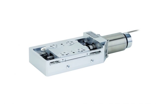
Figure 2: Example of a vacuum-ready linear stage (L-509). Photo: PI
Materials in vacuum-ready products
Common electrical and electronic equipment contains components that either do not suit vacuum applications or only limitedly. These comprise cables, motors, scaling systems, connectors, limit switches and others. Common cables are usually shielded with PVC insulation. Common motors are lubricated with grease or oil, with high vapour pressure containing HCs. And common electronic parts are embedded in plastics with high outgassing rates.
Specific product features should be implemented on all these to avoid outgassing from these components that in total contribute to a clean vacuum environment.
Replacing PVC cables with PTFE or polyimide-shielded braids is technically simple but expensive. Polyimide in particular, has the necessary cleanliness for use in a vacuum, but it absorbs considerable water molecules, which increases the pump-down period drastically. Therefore, only the number of braids necessary should be used for operating the positioning system. The braids should be as short as possible and ideally, the vacuum chamber is also designed for short cables.
Motors modified for vacuum (as shown in Figure 3) have several holes for venting, and are equipped with polyimide-shielded motor coils that ideally have a temperature sensor installed in the motor.
Temperature control is important for two reasons: Firstly, the motor should be operated at a point below excessive heat generation, which means that slow driving is recommended. Secondly, a temperature-controlled bakeout process must be performed by applying current to the motor, at least for UHV systems.
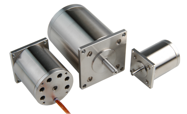
Figure 3: Typical motors for UHV applications – outgassing holes, polyimide-shielded braids, and clean stainless steel surface. Photo: PI
Therefore, all components for UHV stages must be able to sustain heat up to a certain temperature. For example, PI sets this temperature to 120°C for stages with a scaling system, and to 150°C for stages without. Due to the huge number of windings of the motor coils, the amount of polyimide is very high, and therefore, a large amount of adsorbed water must be baked out. Specially designed two-phase stepper motors are implemented in the UHV products as shown in the image above.
Common connectors and limit switches cannot be used in vacuum beyond 10-6 hPa due to their high-outgassing plastic components. They are supplemented by components made of low-outgassing plastics (for HV) or ceramics, PEEK and metal (for UHV), as shown in Figure 4. The pins of the connectors and the contacts of the switches are not soldered, but clamped, crimped or laser welded.
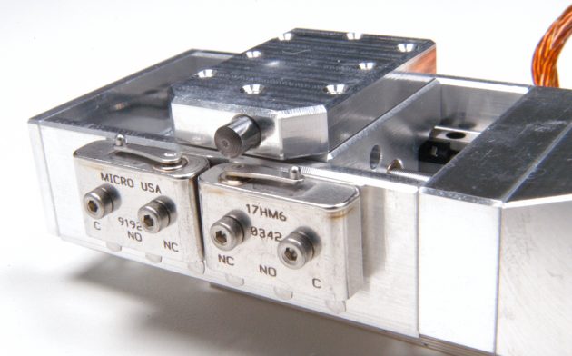
Figure 4: Example of small linear vacuum stage with UHV limit switches. Photo: PI
The selection of materials for the chassis of the positioner is limited. For example, copper-zinc alloys should not be used in vacuum systems. Such materials are replaced by bronze, if possible. Other standard plastic parts are substituted by PEEK, ceramics or metal components for UHV products.
Design for vacuum
Substitution of standard materials with vacuum-compatible materials, as described above, is a strict requirement of vacuum stage design. Another requirement is the reduction and minimization of the surface of the positioner.
The surface of the uncoated body is not sand-blasted for vacuum stages. Covers for protection against contamination are usually not required for vacuum stages. Protective shields for limit switch electronics are not necessary in the case of mechanical limit switches.
The third and very important requirement in vacuum stage design is the prevention of virtual leaks. A virtual leak is a trapped volume connected to the vacuum side of a chamber. The gas in this trapped volume cannot be pumped out easily due to only narrow paths connecting to the vacuum chamber. This results in slow outgassing and appears to be a leak in the vacuum system. Poor design is the major cause of virtual leaks, not only for positioning stages, but for vacuum chambers and vacuum equipment in general.
Trapped volumes are usually caused by unvented or poorly vented blind tapped holes. These are either at the tip of a screw or under the rim of the screw head. Furthermore, holes that are covered, either when mounting the positioner on a base plate or fixing a sample on the positioner, often cause virtual leaks.
In the case of virtual leaks caused by screws, the use of vented screws is recommended. Vented screws have a hole down the length of the screw to avoid trapped volumes, as shown in Figure 5. In this way, the trapped volume can be vented. Furthermore, the head of the screw has a groove to ensure venting of the cavity under the screw head. If the hole is covered by the positioning unit, which then causes a virtual leak, it must have either a perforation or an air vent groove.
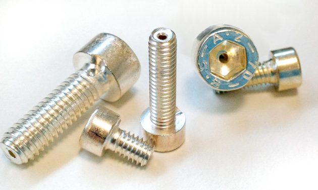
Figure 5: Example for design-for-vacuum – Drilled silver-plated screws for venting of trapped volumes in vacuum. Photo: PI
Vacuum-enabling manufacturing and commissioning processes
Before a vacuum positioner is assembled, all pure metal parts undergo a cleaning process in an ultrasonic bath. Electrical and electronic units are wipe-cleaned. Standard lubricated components such as bearings and guides are degreased, cleaned and lubricated with special vacuum grease. Ultrasonic-cleaned components are dried in a climate chamber.
Assembling of a stage is carried out in a cleanroom or in a laminar flow system. After assembling, the stage must pass a performance test in a clean environment. Vacuum tests are performed for each type of stage, and when vacuum-critical changes are made to the product.
After assembling, the system is packed in vacuum-sealed bags, protected against dirt, air and humidity: First, the stage undergoes a baking process in a climate chamber. After packing and sealing in an inner vacuum bag, the stage is then put into a second, outer vacuum bag which is then vacuum sealed completely.
Accessories for vacuum-ready products
Accessories used within the vacuum environment can also be provided in vacuum versions, such as suitable feedthroughs and cable adaptors. Further accessories such as flanges or connectors are available for vacuum-ready products.
However, for electronic devices, such as controllers and amplifiers, it is recommended to use them outside the vacuum environment.
Stefan Vorndran is VP tactical engineering at PI (Physik Instrumente) LP. He holds an MS in electrical engineering and brings with him over 25 years of experience with nanopositioning and piezo motion applications.
Advertisement
- Weidmüller acquires connectivity company Emphatec
- Taiga Motors to receive $50M in funding toward new Que. plant