Nov. 24, 2014 – I reviewed Radica’s Electra back in 2006. The fact that the product is still active says something about the company and the relevance of the product.
This will be a two-part column on Electra E7, mainly due to the depth of the product, which costs anywhere from $998 to $2,398. One wonders how a drawing program costing $1,000 can be of any assistance in your business. I believe the maturity of the product can offer small to medium-sized automation companies a valuable tool for creating electrical, pneumatic or hydraulic layouts.
Electra is built on Microsoft’s Visio drawing and stenciling product. A valid Visio licence is required to install the package. I installed Visio 2007 before I installed Electra E7 on a Windows 7 virtual machine.
The first place I normally go when preparing a review is the help file to see how much information can be gleaned from there, as well as to get a feel for the level of complication that the product has. This is also an indication of the steepness of the learning curve to expect.
To be clear, the de facto standard for preparing drawings is AutoCAD Electrical. Eplan P8 is another drawing package, but both products represent a big investment in time and money. Electra E7 is an inexpensive entry into automated drawing generation.
As part of the review, I will be taking a peek at MegaFlex Visio stencils, which can be used with Electra E7. These stencils present the full ISA instrument symbols with annotation, so more on this in a later column.
Let’s get started.
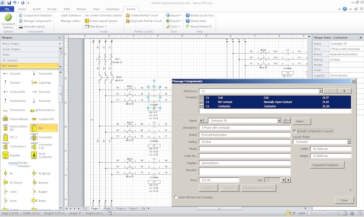
I began by opening up the sample file provided by the company, because the main purpose of a drawing package is to automate the creation of information as much as possible.
Any drawing package of an automation project requires the basics: table of contents, wiring connection schedule, terminal block layouts, bills of material, and cross reference reports, which would be automatically generated by the pages of actual drawings. The creation of pages would be for power (single and three-phase) component control drawings, PLC I/O, and pneumatic and/or hydraulic components.
Conceptually, Electra uses references of symbols, components and groups that are fully object based. How and why you create your drawings is a personal preference, but once the physical system has been designed and handed over for drawing generation, the three-phase equipment is drawn. This includes things like disconnects, main fusing and the like.
You can create your own or use a pre-assembled circuit(s). Should you have multiple similar circuits, a copy/paste function allows you to easily duplicate your efforts. Automatic renaming of wire numbers and terminal blocks occurs, as well as object renaming.
The help file is where I typically start, and there has been a lot of effort put into this one. I also went to the company’s website and found videos on how to navigate through the software.
A very cool feature is the ability to create components from other components — sort of like a macro component. Combining a contactor with two auxiliary contacts and a thermal overload to create a starter component is an example of this. When the component is used, all things automatic — such as terminal points and wire numbers — are updated in the component database.
Electra 7 is written in Microsoft’s VBA as a collection of macros so that all Electra functions are owned by Radica. Visio functions and third-party stencils, such as Megaflex, are still available. I still have to figure out how to take a third-party symbol and integrate it into Electra7 component structure.
The product integrates with Microsoft quite well. Import and export functions exist for the databases that Electra7 uses, so the user can add data and components, and reimport them.
One of the main uses of an electrical drawing package is to document PLC I/O drawings, along with the three-phase and single line data. There are standard drawing blocks for PLC input and output modules, but these blocks don’t differentiate between analog and discrete modules. You can create your own templates, however.
The wiring terminations are presented and then you have to manually insert the devices to create the I/O drawing. Linked wires provide the power supply for the module, though typically from a different page.
I am giving this product some slack since it is a total rewrite of an existing product. I have asked the company for clarification on a number of things, which I will report on next column. As a total revamp of a successful product, I think it deserves it.
This column originally appeared in the November/December 2014 issue of Manufacturing AUTOMATION.