Short circuit protection: Take the right precautions to prevent faults in your fieldbus system
June 16, 2009
By Ian Verhappen
As we all know, if we do not have a reliable control system with availability as close as possible to 100 per cent, we quickly lose faith in the system and circumvent this with “jumpers,” loops in manual and the like that defeat the purpose. The same is true for a fieldbus system. Heck, even “finicky” analyzers have a minimum acceptable availability of 95 per cent.
A key part of any control system is the infrastructure that carries the signals from the field devices to the controllers, because without signals there, will not be data on which to control nor a means to manipulate the final control elements (valves, VFD, VSD, etc.) to adjust the process operating conditions. It therefore amazes me that for the sake of a few dollars, the same people who ask for “redundant everything” to maintain high reliability do not take basic precautions during the design, specification and installation of their fieldbus systems to prevent a single fault from adversely affecting the entire network.
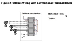
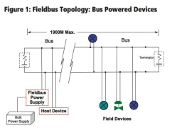 As shown in Figure 1, all the components and devices in a Foundation Fieldbus network are connected in parallel. Knowing this, some companies, under the assumption that they are saving money, use conventional terminal blocks wired in parallel as shown in Figure 2. Such installations, although they adhere to the Fieldbus specifications and are workable, are not, by their nature, reliable.
Why are they unreliable? Without proper precautions, if one device on the network fails to a short circuit, the entire network will also be short circuited – thus causing all devices to effectively fail, including the host, preventing all communications. Without communications, it is not possible to have control and the complete investment in the system will be for naught.
 The Fieldbus Foundation has also realized the importance of reliable connectors and recently released a new standard for testing field device couplers. Phase 1 deals with passive couplers and Phase 2 will cover active couplers such as fieldbus barriers.
What all the device coupler products on the market do have is short circuit protection on every spur connection with a local indicator to indicate a fault condition. Typical field device couplers require the same or less space in a field junction box, so that it is possible to replace existing conventional terminal blocks with a device coupler with the same or more connections.
Short circuit protection continuously monitors the current load on the spur and if it rises above a predetermined limit (usually 40 to 60 mA), the circuit is placed into fault and clamped at this maximum load. If the protection is done by electronic circuitry, it typically automatically resets itself should the condition or fault clear (say in the case of liquids in a line evaporating as the day warms up) while, if fuses are used, manual intervention is required. Manual intervention equates to increased downtime, though depending on the nature of the fault, this difference is negligible when compared to the time to repair the short circuit itself.
The caution with network design, including short circuit protection, is that you must base your design on the assumption of at least one short circuit load. Otherwise, if you are operating close to your system current load and the short circuit occurs, you will have overloaded the power supply limits and still have a complete network failure. The following example demonstrates this.
The current limit for our hypothetical power conditioner is 185 mA. The network has eight instruments at an average current load of 20 mA each. One field device has a current of 10 mA. Short circuit protection load is 40 mA. Therefore the network must include “spare short circuit” capacity of (40 – 10 = 30 mA). Consequently the design device network load is (8 x 20 = 160 mA) + 30 mA for short circuit = 190 mA and therefore the power conditioner is undersized. The solution is to either reduce the number of devices by one, or select devices with lower current draw to manage the energy budget under the 185 mA limit.
As you can see, system integrity needs to be considered from the onset of a project while considering the full lifecycle impact of decisions being made. Integrity brings up the related issue of surge protection, but that is a whole other story to be covered in a future column. As the saying goes, “the chain is only as good as the weakest link,” so please bear this in mind as you design, install and maintain your Fieldbus systems.
Ian Verhappen, P.Eng is an ISA Fellow, ISA Certified Automation Professional, and director, industrial networks at MTL Instruments, a global firm specializing in fieldbus and industrial networking technologies. E-mail him at iverhappen@mtl-inst.com.
Advertisement
- Network monitoring software that gives you the whole picture
- ISA approves major wireless industrial automation standard