Systematic selection: An overview of the most popular rotary motion technologies
July 14, 2016
By David R. Bickert Nexen Group
Jul. 14, 2016 – The ability to provide accurate rotary motion is critical in a wide range of applications in the automation equipment, medical device, machine tool, energy, welding, robotics, automotive, aerospace, semiconductor and heavy equipment industries along with many others.
Some of the key rotary motion technologies available to address these applications include belt drives, cam indexers, planetary gearheads, direct drives and precision ring drives. It’s important to look carefully at the pluses and minuses of each of these technologies in order to ensure that you select the approach that provides the right mix of accuracy, economy, durability, speed, noise, etc., for each specific application. A systematic selection and application process can help ensure that the rotary motion technology that is selected meets all requirements of the application while maximizing the performance and minimizing the cost of this critical component.
Belt drives
Belt-driven rotary tables generally offer the advantages of high speed and low cost in rotary positioning applications. Belts are typically made of fiber-reinforced elastomer and contain teeth that interface with rotor pulleys to efficiently transfer torque and prevent slipping. Typical belt-driven tables offer speeds up to 1,000 rpm, continuous torque to 6.6 N-m and resolution down to 0.16 arc-second using ring encoders. Additional advantages of belt-driven systems include the fact that they generate relatively little noise and require relatively little maintenance. Due to the potential for elongation of the belt, positioning accuracy of belt drives is often inferior to other alternatives, such as planetary gearheads or precision ring drives. In summary, belt drives are a good choice for applications that require high speed and low cost, however, offer relatively poor life and limited load capacity, accuracy and rigidity.
Cam indexers
Cam indexers have been used in rotary positioning applications for many years and are frequently used in dial machines, conveyors and linkages. There are two types of cam indexers. The most common is the fixed index cam indexer, which does not use a servo motor. With fixed index cam indexing, a mathematical motion curve is machined into the cam to provide accurate positioning to a discrete number of defined positions. During rotation of the cam indexer, maximum displacement velocity usually occurs around the midpoint of the index cycle. Any fluctuation in cam speed tends to generate increased output torque at the high displacement portion of the cycle. These torque fluctuations sometimes generate irregular rotary motion during indexing, as well as audible noises when the indexer approaches a station. These problems can be avoided by maintaining shaft speed within a very narrow range. Fixed index cam indexers provide high-precision positioning at a reasonable cost for applications that will always index to the same angle and do not require high acceleration.
Fully programmable cam indexers combine a servo motor with a cam-driven index drive. This type of cam indexer is advantageous when a flexible motion pattern is required, such as when two different products that require different indexing patterns are run on the same machine. A fully programmable cam indexer is also beneficial for applications where extremely fast positioning is required, followed by a long dwell period.
Planetary gearheads
Planetary gearheads are frequently used on motion control applications that require a high torque to volume ratio. Planetary gearheads utilize an arrangement in which one or several planet gears rotate around a pinion or sun gear. The planet gears rotate within an internal gear that is most often cut into the internal diameter of the gearhead. The planetary gear decreases the reflected load inertia at the motor shaft by the inverse of the square of the gearhead ratio, which increases the control system responsiveness and generally provides more consistent and accurate motion response. The planetary gearhead offers the advantage of a wide range of gear ratios which, in many applications, will make it possible to operate both the motor and the application at their ideal speed. Single-stage planetary gearheads typically provide ratios from 3:1 to 10:1. Helical gearing improves the performance of a planetary gearhead over spur gears by increasing the contact load line. The potential drawbacks of planetary gearheads include their relatively high cost and the fact that they contain backlash and can be damaged by shock loads.
Direct drive
A direct drive rotary motor is typically a large diameter permanent magnet servo motor. The unique characteristic of direct drive rotary positioning systems is that the motor is connected directly to the load eliminating all mechanical transmission components. Rotary positioning systems built around direct drive rotary motors are wide used in the factory automation, medical equipment and energy industries. Direct drive systems generate energy savings by operating at high levels of efficiency because the elimination of the power transmission system provides a substantial reduction in friction. Direct drive systems also have fewer components, which often reduces maintenance requirements and provides quieter operation because there are few parts that can vibrate. The elimination of the gear train also reduces backlash and compliance. Sometimes a direct drive system is combined with an encoder mounted on the rotary table to provide precision positional feedback and a high stiffness bearing to improve positional accuracy and repeatability, however, this approach is quite expensive relative to other technologies discussed here. While direct drive motors provide high levels of performance and efficiency, they are limited by low load capacity, high cost and relatively low accuracy without costly ring encoders.
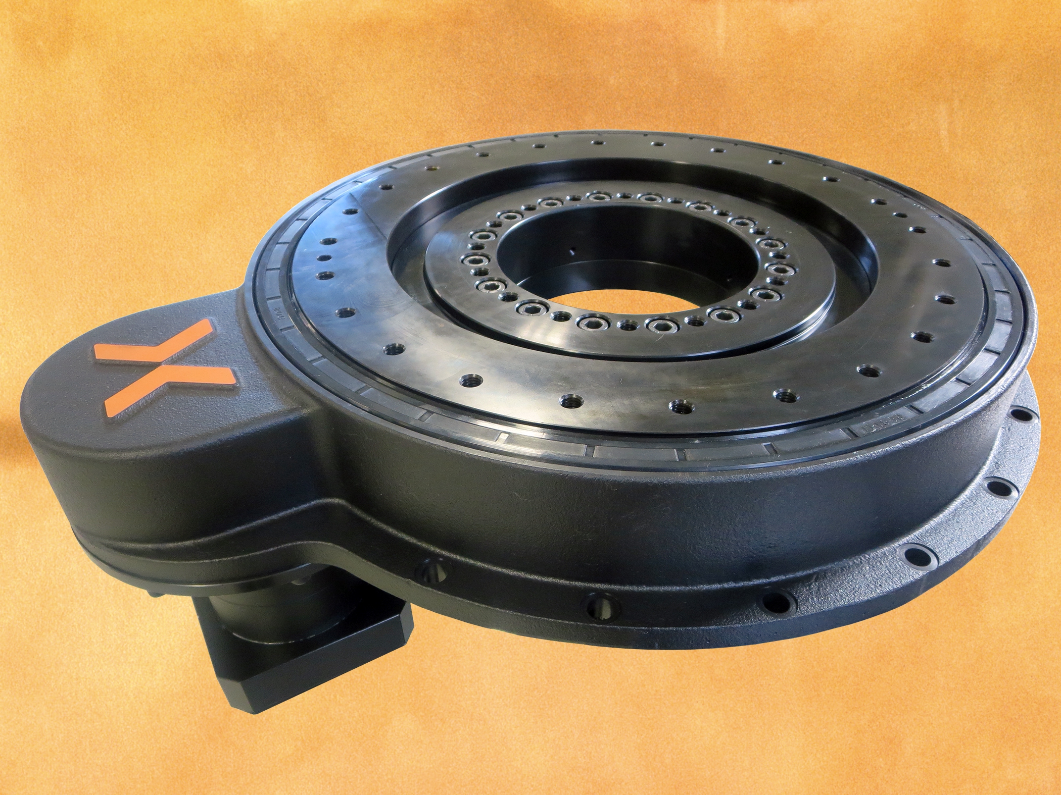
Roller pinion systems
The precision ring drive is a somewhat new type of rotary positioning system featuring a unique roller pinion/toothed rack combination that delivers high accuracy positioning with zero backlash and virtually eliminates cumulative error. Precision ring drives at first glance look similar to ring and pinion sets but, instead of spur gear teeth, bearings supported rollers engage the ring teeth. The rollers engage a tooth profile designed to match the pinion’s path, providing friction-free meshing that allows the pinion to be pre-loaded into the ring, eliminating mechanical clearance. The rollers approach the tooth face on a tangent path and then smoothly roll down the face. Each tooth is precisely measured relative to the first, eradicating cumulative error and maintaining high positional accuracy. The resulting smooth rolling friction provides 99-per-cent efficient rotary motion. Due to the smooth way the rollers engage the rack teeth, the new approach generates very low noise and vibration. The system is whisper quiet at low speeds and produces less than 75 db noise at full speed.
Drives are offered with ratios ranging from 64:1 to 220:1. Peak torque goes from 563 to 1,936 Nm. Accuracy ranges from ±11 to ±35 arc-sec, with repeatability of ±4.2 to ±1.2 arc sec. Unlike traditional cam-drive systems, the precision ring drive can start and stop at any incremental position. Users can change the motion profile simply by loading a new servo drive program. The roller pinion system driving the precision ring drive also allows the application of maximum acceleration or deceleration at any point without risking damage. The precision ring drive is capable of speeds up to 300 rpm and can handle peak torque inputs at any time, resulting in index speeds up to two times faster than other types of positioning systems. A given size product in a premium model can support a maximum dynamic load (N) of 1,000. The drive mounts on a table supported by cross-roller bearings rated for 1,575-kN loads. The roller pinion system requires little maintenance. The pinion consists of 10 or 12 needle-bearing supported rollers that are sealed and lubricated for life. The ring is lubricated with a high performance light grease at installation and then every six months or 2 million pinion revolutions; no messy oil baths are required. Pinion life is rated at 60 million revolutions and the pinion gear can usually be replaced numerous times before the ring gear needs replacement. The ring drive has a large open centre that allows users to easily mount equipment and cabling in the centre of the rotating plate.
Conclusion
Rotary motion technologies, such as belt drives, cam indexers, planetary gearheads, direct drive systems and roller pinion systems each offer their own unique mix of advantages and disadvantages. In order to apply the correct type of rotary motion technology in a particular application, the design engineer should carefully consider the specific capabilities of each alternative. Selecting the right technology can improve performance, ensure long life and reduce the overall cost of the assembly.
David R. Bickert, regional sales manager for Nexen Group, has more than 24 years of work experience in automation and motion control. He has a bachelor of science (B.Sc.) degree in mechanical engineering technology from Penn State University and an M.B.A. from Fontbonne University. Bickert has worked at Nexen Group for more than 13 years.
This article was originally published in the May 2016 issue of Manufacturing AUTOMATION.
Advertisement
- HMI checklist: What to consider when shopping for an HMI solution
- Schneider Electric crowned Tech Company of the Year at VIATEC Awards 2016