Ensuring power and process stability in manufacturing environments
June 27, 2017
By Yves Bouhadana Riello UPS

Jun. 27, 2017 – Robotics, variable frequency drives (VFDs) and programmable logic controllers (PLCs) are prevalent in many manufacturing environments. These microprocessor-based control systems have enabled plants to automate many functions and processes, increasing repeatability and precision in a wide array of industries.
These same plants, however, are also more susceptible to variations in power such as anomalies or fluctuations caused by under- or over-voltages, interruptions, transients, waveform distortion, “noise” or frequency variation.
An interruption in power to a PLC, for example, can mean lost production due to downtime, increased scrap rate or rework costs, as well as clean-up. Depending on the plant, the financial impact can be substantial. It is critical for manufacturers to look at the causes of these most common power anomalies and how to safeguard against them.
Manufacturing processes that rely on motor controllers and VFD systems require a stable DC voltage to ensure smooth operation.
A loss of quality DC power would disable the appropriate speed and torque control of the motors that drive the manufacturing process. A process that uses a conveyor indexing between manufacturing stations, for example, would shut down when power to the conveyor motor is interrupted. Depending on the duration of the outage, work in process on the conveyor at the time might need rework or to be scrapped.
Ideally, power coming from the utility company would have a clean waveform. Viewed on an oscilloscope, this clean sine wave would look like Image 1.
The waveform would look similar whether the voltage was 480V 60HZ, 240V 60HZ, or 208V 60HZ, which are the most common three-phase voltages in North America. Incoming line voltage can be distributed as is or stepped down as needed (480V to 208V, for example, or 240V to 120V). A load requiring a new neutral is more sensitive to anomalies than loads not requiring a new neutral. The most common primary power disturbances are shown here along with their waveforms as seen on an oscilloscope.
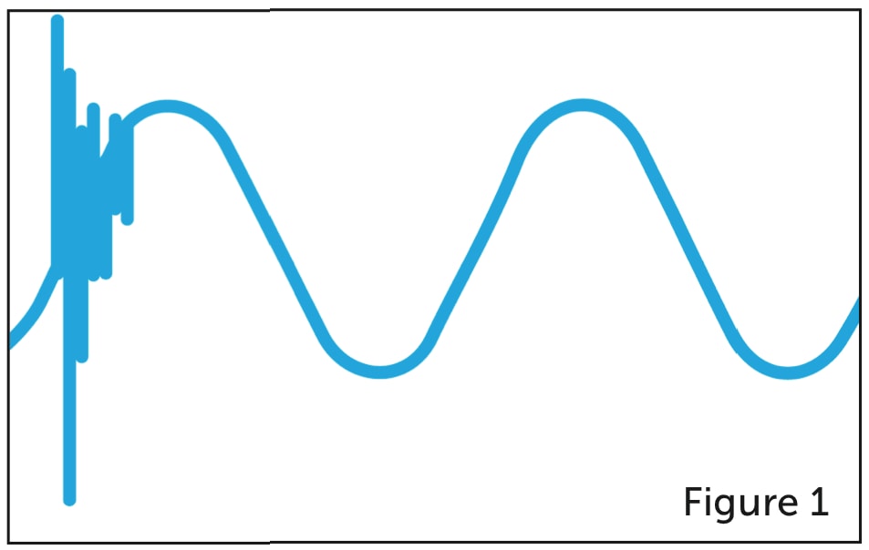
1. Transients: This anomaly occurs during switching of high current loads such as when another motor switches on within the vicinity. Refer to Figure 1.
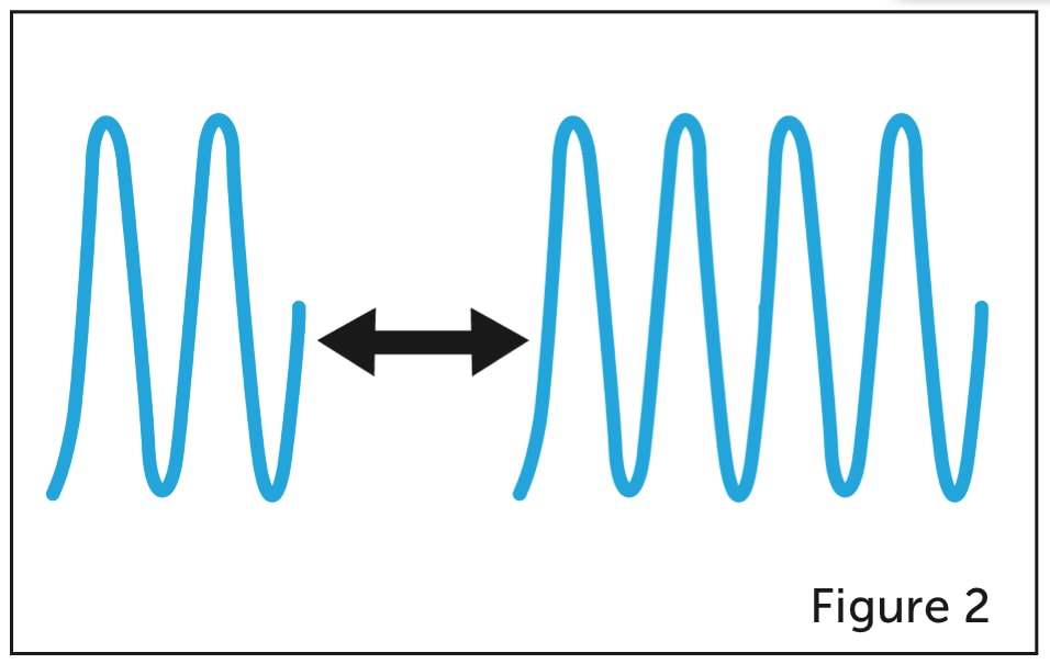
2. Interruptions: A momentary or longer-term power outage. Blackouts can occur when utility power lines are downed due to storms or accidents or occurrences which temporarily stop the flow of electricity in the power lines. See Figure 2.
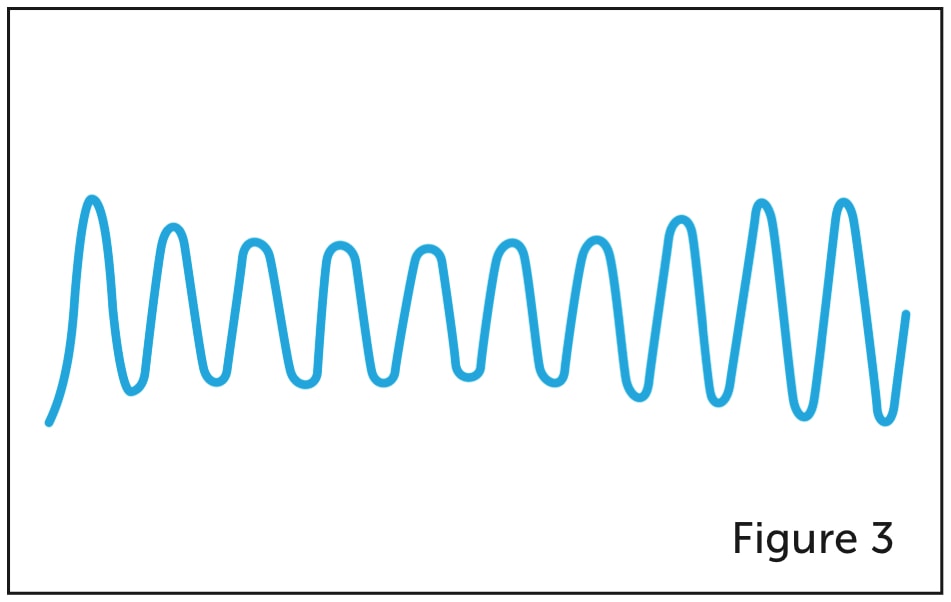
3. Under-voltage or sags: Here the “ramping up” of high current loads overloads the power source, causing a damping of the voltage or causing it to sag. These typically occur when multiple pieces of equipment are powered up simultaneously, at the start of a shift, for example. Refer to Figure 3.
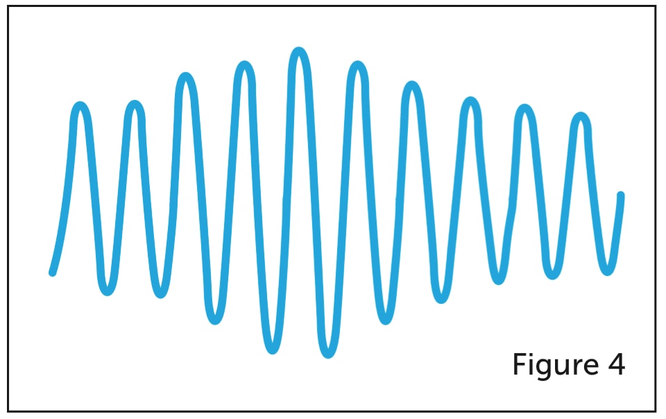
4. Over-voltage or swells: A rapid load reduction provides a surplus of power in the utility, delivering a swell of power to the equipment still running (Figure 4). This occurs at the end of a shift when a lot of equipment is powered down simultaneously. The system is used to supplying a higher level of power and when that demand is quickly reduced, the excess voltage is delivered to whatever equipment remains operating.
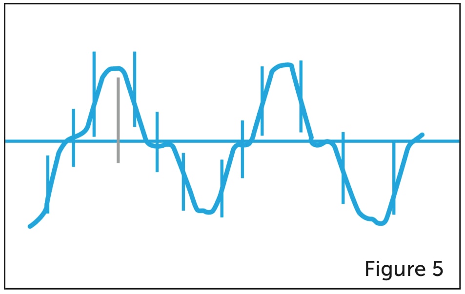
5. Waveform distortion: Non-linear loads like iron motor cores disrupt and distort the waveform, yielding a non-uniform sine wave; a low power factor input from a PLC is another example. See Figure 5.
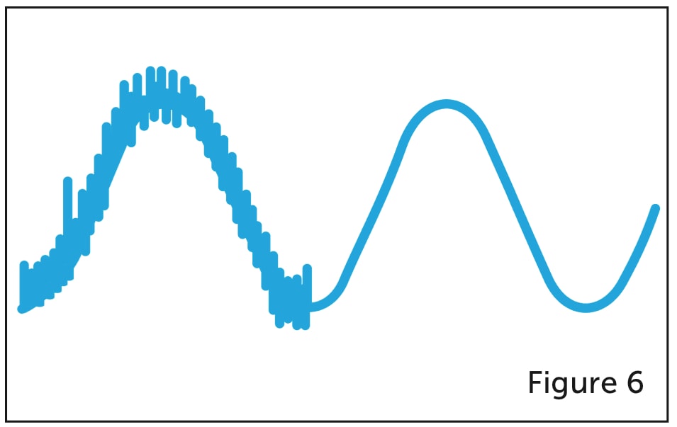
6. Noise or electromagnetic interference (EMI): This is typically caused by high current radio frequency waves introduced into the system. Radio frequency noise can result from radios used in feedback loops; refer to Figure 6.
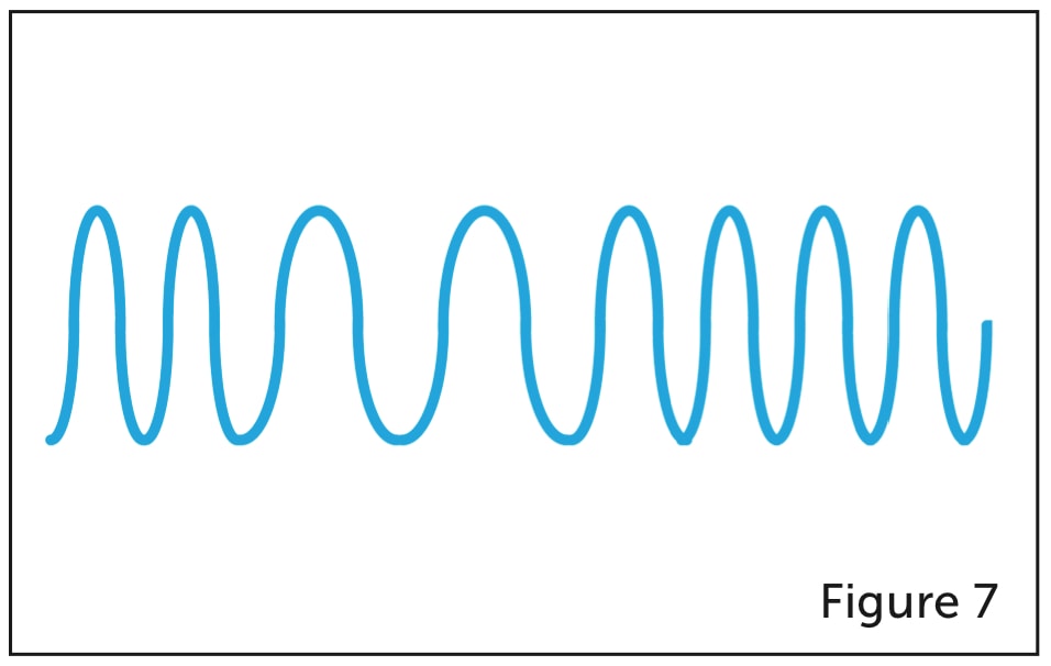
7. Frequency variation: This is generally caused by the acceleration of deceleration backup of generators (Figure 7).
VFDs are often installed on the plant floor in rugged environments where switching constantly occurs — and with it come the inherent transients, sags and swells. Since these anomalies impact the DC output of VFD, the speed and torque of the downstream motors are also impacted, as well as the manufacturing process.
If the power supply is stable, and no outages are anticipated, supercapacitors can store energy to compensate for sags. If outages are anticipated, then batteries can compensate for outages and interruptions. Batteries offer ride-through times (supplied power during the disruption of utility power) of six to 30 minutes, versus supercaps which have a ride-through time of seven to 24 seconds.
Stability of the DC Bus can be achieved in several ways. An uninterruptible power drive (UPD) rectifies the AC voltage, stores energy in capacitors and supplies that energy to the DC Bus when a sag is detected, resulting in a limited deviation of the DC voltage at the DC Bus.
If the DC Bus is not accessible, or multiple VFDs need to be protected on the same electrical network, then an uninterruptible power system (UPS) provides power at the input of the VFD, resulting in a stable DC voltage. Double conversion UPS systems with capacitors, which convert AC power to DC power then back to AC power, provide a clean waveform to the VFD as well as 15 seconds of outage ride-through.
Yves Bouhadana has more than 26 years in the quality power industry, having worked for Emerson Network Power and currently Riello UPS. He is a graduate of University of South Florida with a B.Sc. in Electrical Engineering. Bonitron and Riello UPS have partnered to supply power quality solutions for the industrial manufacturing industry.
This article was originally published in the June 2017 issue of Manufacturing AUTOMATION.